Machines
Guiding the Cleaning Rod on an Optical Print Head
Replacing spinning laser mirrors with solid-state light bars solved printer vibration, but it placed fragile micro-optics directly in the path of airborne toner dust.

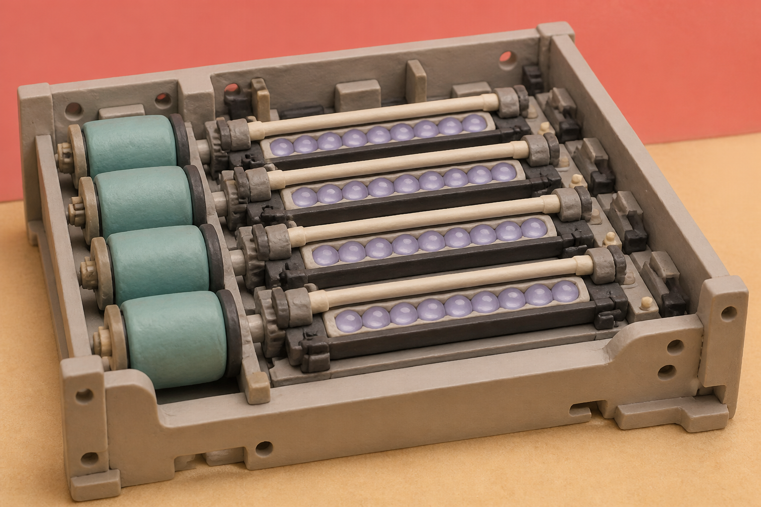
What changes in this design
People might imagine that a cleaning tool simply slides across optical parts by hand or rests loosely in a basic holder without restricted boundaries.
In this record, a dedicated guide includes two distinct restricting portions that physically bound the cleaning rod, preventing it from shifting either toward or away from the print head.
Controlling the exact path of the wiper prevents mechanical interference while ensuring the lens surface receives proper cleaning.
The vanishing polygon mirror
In 1981, engineers at OKI demonstrated the first printer to replace a spinning laser mirror with a static array of light-emitting diodes. Five years later, their OPP6220 model brought that concept to desks at 240 dots per inch and sixteen pages per minute. For decades, desktop laser printers relied on a motorized polygonal mirror spinning at thousands of revolutions per minute to bounce a laser beam across a photosensitive drum. The mechanism worked, but it was noisy, physically bulky, and vulnerable to vibration. Replacing that optical maze with a single stationary bar packed with thousands of microscopic light sources promised a cleaner, faster machine.
I spent an afternoon looking through old printer teardowns to see where all the moving parts went. When you drop the rotating polygon mirror, the long optical path disappears. Instead of reflecting light across several inches of empty air through complex corrective lenses, a solid-state print head sits right against the drum. Over the decades, solid-state arrays progressed from early desktop units to high-density heads reaching 2400 dots per inch, eventually leading to systems designed around organic light-emitting diodes capable of 4800 by 2400 dpi.
Two millimeters of glass
Collapsing that distance required a different kind of lens. Nippon Sheet Glass solved the problem by commercializing the SELFOC Lens Array, a dense row of gradient-index glass fibers with individual diameters as tiny as 300 micrometers. Standard curved lenses need space to focus light, but gradient-index optics use a parabolic radial variation in refractive index to bend light internally through flat-ended rods.
The engineering trade-off that caught my attention sits right at the focal plane. These micro-lens arrays produce an erect, one-to-one image without bulky mirror assemblies, but their working distance is tiny, often between 2 and 30 millimeters from the photosensitive surface. To form a sharp image, the flat glass faces must sit nearly flush against the drum.
A cloud of three-micron dust
That close proximity creates an immediate environmental hazard inside the chassis. The electrophotographic process runs through six continuous stages: charging, exposure, development, transfer, fusing, and cleaning. To sharpen image quality over the years, manufacturers shifted from crushed toner particles measuring 14 to 16 micrometers down to chemically grown emulsion-aggregation particles that measure just 3 to 5 micrometers.
When we look at the electrophotographic cycle, every print run sheds a cloud of ultrafine powder. Doctor blades scrape the drum, mechanical seals wear down, and sub-micrometer airborne particles escape into the internal cavity. Industry standards like ECMA-328 and ECMA-370 establish strict chamber tests to measure these volatile organic compounds and ultrafine dust emissions. Even inside an environmentally certified machine, electrostatic toner dust drifts onto any nearby surface. When that dust settles on a lens array sitting two millimeters away, it blocks the light emitters and leaves blank vertical streaks across the printed page.
Restraining the cleaning wand
That brings us to a recent patent application, US20260259517A1, published under the title "Image Forming Apparatus." The filing tackles what happens when an operator tries to wipe toner streaks off the optical head. Most modern solid-state printers include a long cleaning rod that slides along the lens array to scrape off accumulated powder. But gradient-index glass arrays are brittle, flat, and vulnerable to surface scratching or mechanical misalignment.
If an operator presses the cleaning rod too hard against the glass, the wand can scratch the 300-micrometer lens faces or knock the print bar out of its narrow focal window. If they pull too far back, the pad misses the toner entirely. The patent's solution is a specialized guide member equipped with distinct first and second restricting portions. These physical brackets restrict the cleaning rod's movement in both directions, preventing it from straying away from the lens array while simultaneously blocking it from pressing too hard against the optical glass.
The open question
I could not find an easy way around this geometric trap in the published literature. As imaging resolutions climb to thousands of dots per inch, the optical tolerance on solid-state print heads becomes unforgiving. Yet the machine must still operate inside a dirty, dry-powder environment without requiring a technician every time a vertical streak appears.
That tension between micro-scale optics and brute mechanical wiping is, I think, the real story here. It reveals how much of our solid-state precision still depends on crude physical safeguards. Will print bar design eventually find an optical coating or sealed airflow that keeps three-micron toner off the glass entirely, or are we permanently stuck designing plastic brackets to protect high-precision optics from the people trying to clean them?
Sources
Reporting for this piece drew on the published filing and the references below.
- US20260259517A1 - Image Forming Apparatus
- SLA - SELFOC Lens Array | Nippon Sheet Glass
- SELFOC Product Introduction | Nippon Sheet Glass
- LED printer - Wikipedia
- Toner (printing) - Wikipedia
- Laser printing - Wikipedia
- Gradient-index optics - Wikipedia
- ECMA-328: Determination of Chemical Emission Rates from Electronic Equipment
- ECMA-370: TED - The Eco Declaration
The record, briefly. US20260259517A1, “Image Forming Apparatus” An image forming apparatus includes a photosensitive member, an optical print head with a light-emitting element substrate and a condensing lens array, a longitudinal cleaning rod to clean the lens emission surface, and a guide member to guide the rod against the lens. The guide member includes first and second restricting portions to restrict cleaning rod movement away from and toward the optical print head.
More angles on this
- CPC G03G: Electrography; electrophotography; magnetographyThe official classification family this record was filed into, published in the USPTO Cooperative Patent Classification scheme.
- Inside bilingual augmented reality lampAnother reading from the neighbouring G03B classification family, apparatus or arrangements for taking photographs or for projecting or viewing them.
- Portable And Low-Cost Microscopic Imaging Device Makes a Small Case for Better TimingAnother reading from the wider G02B classification family, optical elements, systems or apparatus.
- A reticle stage with a shield that travels with it, and what two positions make legibleAnother reading in the same Machines category on this site.
Read around this one:Public patent recordUSPTO published figure