Objects
A Rivet Tool Puts Its Own Shadow on Notice
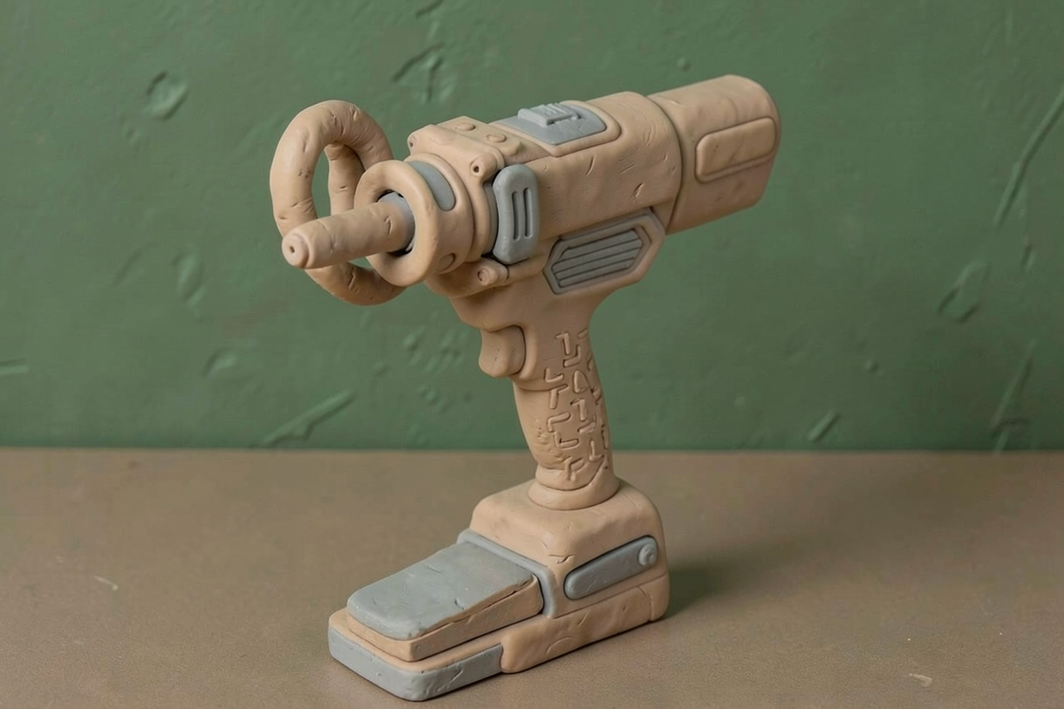
A ring of LEDs surrounds the rivet tool’s nose, while a two-stage trigger offers light before the pull. The details go beyond adding a lamp.

First, the setting
Blind riveting joins parts by pulling a mandrel through a rivet so its sleeve deforms against the workpiece. The tool must grip, pull and release that mandrel while its forward nose remains positioned at the fastening point.
Access and visibility both matter when positioning a fastening tool. The nose must reach the work while the operator sees where it sits. Lighting position, control timing and feedback can therefore influence the handling task alongside the pulling mechanism.
What changes in this design
A lamp beside a long rivet-tool nose can have its light obstructed by that nose before reaching the work.
The disclosed ring surrounds the nose, with distributed emitters and a lens arrangement; one trigger embodiment illuminates before it powers the motor.
Emitter placement addresses the shadow geometry, while trigger timing addresses when the operator can see the fastening point.
The tool is standing in its own light
I like a tool improvement that begins by noticing what the tool itself is obstructing. A cordless rivet gun needs a nose long enough to reach the fastening point. Put a small lamp beside that nose and the same useful length can throw a shadow over the work. The tool has brought a light and then parked in front of it.
This application addresses that awkward arrangement with a ring light around the nose piece assembly. Light travels toward the work from positions all around the central shaft, rather than relying on one point beside it. The stated aim is illumination without a discernible shadow caused by that assembly. It is a particular shadow problem, with a particular geometric answer.
The description offers more than a circle in a drawing. It specifies a ring-shaped circuit board, LED spacing, a protective lens, staged trigger operation and optional color indications. Those details turn a familiar accessory into a question about how the whole tool behaves before, during and after a rivet is set.
First, what the nose is doing there
In the described blind-riveting operation, the rivet’s protruding mandrel enters the nose piece. Internal jaws grip it. A motor drives a reduction mechanism and a leadscrew, converting rotation into the backward movement that pulls the mandrel while the nose presses against the rivet head. The sleeve compresses to secure the workpiece, then the mandrel breaks at its designed weak point.
The separated stem still needs somewhere to go. The embodiment includes a passage to a collection container at the rear; after release from the jaws, tilting the tool lets gravity help it slide into that container. Riveting is one of those jobs in which a small broken piece means things have gone according to plan.
That working assembly occupies the middle of the light’s route to the workpiece. Moving illumination around its circumference is therefore directly related to the tool’s mechanics. The nose remains where it needs to be, and the light approaches the fastening point from several surrounding positions.
A ring needs spacing and a lens
The illustrated light source uses LEDs on an annular printed circuit board, with the nose assembly passing through its central opening. A lens assembly covers the source. The description includes diffusing lenses that spread light from the individual emitters so the output appears to come from one ring, plus seals and protective parts intended to keep contaminants away.
LED spacing is a surprisingly specific part of the explanation. One embodiment sets the circumferential gap between LEDs below the diameter of the nose assembly. The disclosure argues that this keeps the remaining light more evenly distributed around the axis as the nose blocks light from individual emitters. A widely spaced arrangement, it explains, can leave different angular positions receiving different illumination.
I find that detail more persuasive as engineering than merely counting the lamps. The intended result depends on where the emitters sit and how their light is distributed. A complete circle on the parts list is only the beginning; the workpiece receives the actual pattern. That is the pattern I would want to compare with a single-point lamp.
A little trigger, then a rivet
The proposed two-stage trigger makes room for looking before pulling. In that embodiment, a partial squeeze powers the ring light while leaving the motor off. A full squeeze powers both. One described non-contact arrangement senses a moving magnet with Hall-effect sensors, allowing the controller to distinguish trigger positions. Other embodiments use contact switches or a separate lighting control.
The light can also remain on after the trigger is released, giving the operator illumination while moving to the next fastening point. Fifteen seconds is one example in the description, among several possible durations. I appreciate the sequence: see the position, perform the pull, then see where to go next. A lamp that clocks off at the exact instant the motor does has impeccable punctuality and questionable timing.
Some versions give the ring a second job as a status indicator. The controller can change its color after detecting a successful mandrel separation or an unsuccessful operation. The description links one success indication to a sudden drop in motor load, and a failure indication to overcurrent. It also proposes cycle-count reminders for emptying the mandrel container or performing maintenance.
The useful test is at the fastening point
What holds this design together is attention to the work at the front of the tool. The ring tackles a shadow cast by the working assembly; the trigger offers a chance to illuminate before engaging the motor; continued lighting helps with the next position. The optional colors bring feedback into that same area of view.
Those are described functions, rather than measured production gains. I would compare illumination at different working distances and angles, then check whether the trigger stages and status colors remain easy to distinguish during ordinary handling. Seeing the rivet clearly and determining the quality of a finished joint are different tasks, even when the tool reports that the mandrel separated.
The practical appeal is modest and clear. Keep the essential nose in place, distribute light around it, and make the lighting available when the operator needs to look. An improvement does not have to change how a rivet holds two parts together. Sometimes it starts by letting the person holding the tool see the parts.
The record, briefly. US20260264134A1, “Cordless Rivet Tool With Ring Light” The cordless rivet tool places a battery-powered ring light in its housing around the nose piece assembly, directing distributed light along the nose axis to avoid a discernible shadow caused by the assembly. Described embodiments use LEDs on an annular PCB, circumferential spacing smaller than the nose diameter, a protective/diffusing lens and a two-stage trigger: partial pull for light, full pull for light and motor. Non-contact trigger variants use a moving magnet and Hall-effect sensors. Lighting may remain on after release; color variants can indicate mandrel separation, failure or maintenance reminders using motor-load/current or cycle-count information. These are disclosed arrangements, without quantified handling or productivity results.
More angles on this
- CPC B21J: Forging; hammering; pressing metal; riveting; forge furnacesThe official classification family this record was filed into, published in the USPTO Cooperative Patent Classification scheme.
- The Potato Product Makes Its Entrance in SlicesAnother reading from the neighbouring B21C classification family, manufacture of metal sheets, wire, rods, tubes, profiles or like semi-manufactured products otherwise than by rolling.
- Quiet Alignment at the WellheadAnother reading from the wider B09B classification family, disposal of solid waste not otherwise provided for.
- When Player Traits Become an Arrangement ProblemAnother reading in the same Objects category on this site.
Read around this one:Public patent recordUSPTO published figure