Objects
Managing Axis Rotations And Tool Paths Along Inclined Planes
A recent patent filing wants CNC controllers to solve multi-axis toolpath angles in real time, but shortest-path math carries its own mechanical traps.

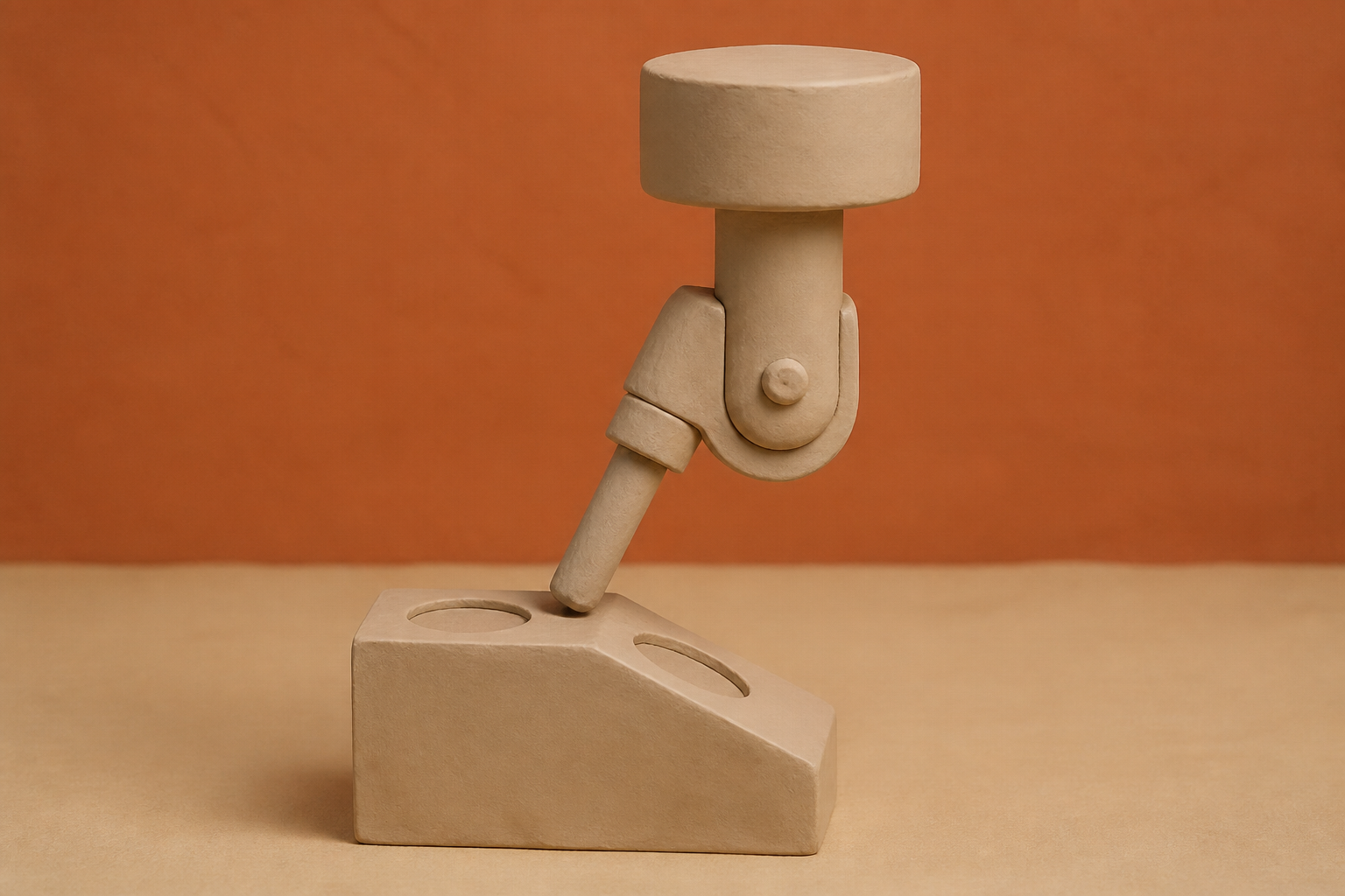
What changes in this design
A reader might assume that pivoting a tool into position is a straightforward maneuver where axes simply turn directly toward the target. In practice, moving multi-axis machinery across an inclined surface can easily cause physical interference if the rotation path is not planned around the slope.
The setup in the record uses two specialized steps. First, a calculation unit figures out the angle combinations required to set the tool at a specific tilt relative to the plane. Next, a determination unit picks the exact direction and count of turns for multiple rotational axes to minimize the total movement amount or travel time.
Planning rotation paths carefully matters because reorienting equipment on a slope carries a real risk of mechanical interference. By choosing specific axis counts and directions, the system shifts the tool into its new orientation without collisions while keeping total movement time or distance as low as possible.
Five axes and a tilted plane
A five-axis milling head does not simply move up, down, and across. It tilts, swivels, and rotates around a workpiece, combining three linear axes with two rotary motions like table tilt or spindle pivoting. To keep a spinning cutting tool positioned at an exact angle against an inclined plane, the machine controller must constantly map cutter location vectors into joint space using four-by-four transformation matrices. The payoff is obvious: multiaxis setups cut cycle times, improve surface finishes, and eliminate the need to reposition a part manually between cuts. The danger is that a single wrong calculation when changing direction can drive a high-speed spindle straight into a mounting trunnion.
When we look at how legacy manufacturing systems handled this, the division of labor was strictly separated. An engineer programmed toolpaths offline in computer-aided manufacturing software, which converted 3D geometry into lines of ISO 6983 G-code. That older format stripped away high-level geometric features and workplane intent, leaving the physical machine to execute blind coordinates without knowing what shape it was actually cutting. If an unexpected clearance issue arose on a tilted surface, the machine had no way to recalculate its own orientation on the fly.
Putting the solver on the machine
That limitation is what makes patent application US20260259543A1, titled "Processing Device, Program, And Processing Method," worth exploring. The published record describes a system designed to prevent tool interference when changing a tool's direction relative to an inclined plane. Rather than relying entirely on pre-computed instructions from an external computer, the filing outlines a processing device with a calculation unit that determines angle combinations for positioning the tool at a prescribed angle relative to a plane. A determination unit then calculates the optimal rotational direction and rotation count across multiple axes to minimize either total rotational movement or elapsed time.
The detail that caught my attention in the published record is where the computation takes place. Modern digital standards like STEP-NC have long aimed to embed feature and workplane information directly into machine execution. By embedding inverse kinematics solvers and angle optimization inside the controller itself, similar to open architectures used in LinuxCNC, a machine tool can evaluate its own rotational joint limits and adjust orientation in real time. I suspect many machine shops would welcome anything that stops an expensive crash on a steep bevel.
The ambiguity of Euler angles
Choosing the shortest rotational path to an inclined plane sounds straightforward until you look at the math behind spatial rotations. When a system uses Euler angles to describe three-dimensional orientation, there is rarely a single answer. Multiple distinct angle combinations can position a cutting tool at the exact same orientation relative to a surface. Picking the combination that requires the smallest angular movement seems logical, but minimizing joint travel in isolation creates unexpected mechanical traps.
In our review of the research on 5-axis kinematics, that shortcut is where things get tricky. A 2009 study by Lavernhe and colleagues showed that optimizing tool axis orientation requires balancing geometric precision against physical velocity and acceleration bounds. If a controller only searches for the shortest angular delta without accounting for axis acceleration limits, the physical machine may shudder or stall while trying to execute rapid rotational shifts.
Gimbal lock and velocity spikes
The deeper hazard lies in mathematical singularities. When two rotary axes align, three rotational degrees of freedom suddenly collapse into two, creating gimbal lock. In those singular regions, standard inverse kinematic equations break down.
Research by Zhang and colleagues into multi-axis motion planning demonstrated that nonlinear mapping near singular points turns smooth toolpaths into wild velocity spikes and discontinuous axis movements. An automated solver aiming for the shortest path can inadvertently steer the rotary table straight through a singularity. When that happens, the machine controller demands near-infinite rotational speed from its drive motors to maintain the required tool angle, which can ruin the workpiece or trigger an emergency stop.
Where the risk actually sits
What I find missing from the patent is an explicit defense against these singular regions. Calculating angle combinations to minimize travel time or avoid collisions on an inclined surface is a sensible evolution for intelligent controllers. Yet if a controller-level solver picks a minimal rotation path that crosses a singularity, the cure might be as destructive as the original collision risk.
Coordinated multi-axis control is already sensitive enough to fall under multilateral dual-use export controls, such as the Wassenaar Arrangement, because high-speed contouring across five or more axes requires exceptional precision. Moving trajectory calculations from offline software into real-time machine hardware is the right technological path. But until these onboard solvers incorporate singularity-aware motion planning alongside basic shortest-path calculations, I cannot say whether an automated angle selection on a tilted plane will protect a machine tool or push it into a mechanical seizure.
Sources
Reporting for this piece drew on the published filing and the references below.
- US Patent Application US20260259543A1 - Processing Device, Program, And Processing Method
- 5-Axis Kinematics - LinuxCNC
- Multiaxis machining - Wikipedia
- Optimisation of tool axis orientation in 5 axis machining taking into account kinematical constraints
- Singularity-aware motion planning for multi-axis additive manufacturing
- Toolpaths Programming in an Intelligent Step-NC Manufacturing Context
- Euler angles - Wikipedia
- Gimbal lock - Wikipedia
- Kinematics - LinuxCNC
- Wassenaar Arrangement - Wikipedia
The record, briefly. US20260259543A1, “Processing Device, Program, And Processing Method” A processing device, program, and processing method prevent tool interference when changing tool direction relative to an inclined plane. The device includes a calculation unit that calculates angle combinations for positioning the tool at a prescribed angle relative to a plane, and a determination unit that determines rotational direction and count for multiple rotational axes to minimize rotation movement amount or time.
More angles on this
- Inside systemAnother reading from the same G05B classification family, control or regulating systems in general.
- A Coffee Basket's Quiet Second ActAnother reading from the same G05B classification family, control or regulating systems in general.
- CPC G05B: Control or regulating systems in generalThe official classification family this record was filed into, published in the USPTO Cooperative Patent Classification scheme.
- A Field Robot's Route Plan Reads Less Like a Map and More Like a Rehearsal ScheduleAnother reading from the neighbouring G05D classification family, systems for controlling or regulating non-electric variables.
- Leveling The Foundation For An Object Holder ElectrodeAnother reading from the wider G03F classification family, photomechanical production of textured or patterned surfaces, e.g. for printing, for processing of semiconductor devices.
Read around this one:Public patent recordUSPTO published figure