Objects
Measurement Method, Observation Device, And Program Makes the Next Move Easier to See
Electric motors destroy their bearings from the inside out, and a new patent application wants to turn the steel balls themselves into real-time oil sensors.

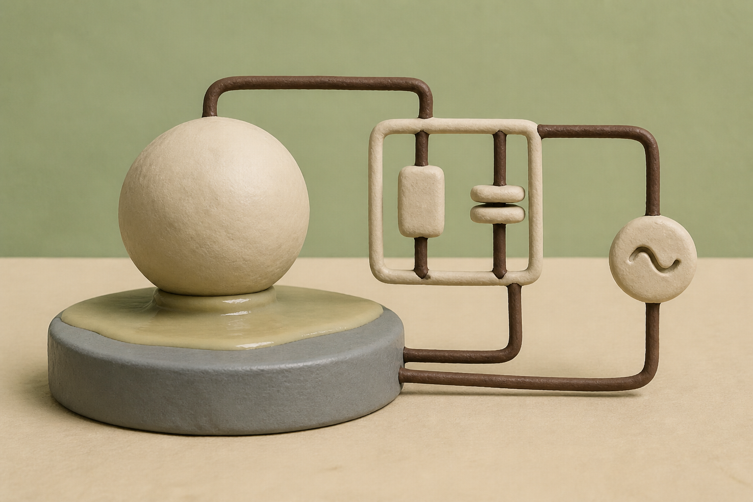
What changes in this design
A reader might assume that checking whether moving parts touch requires taking equipment apart or inspecting surfaces after wear has already happened, rather than monitoring the protective fluid directly while parts move.
Instead of physical inspection, this record details sending an alternating voltage through the components and lubricant. It measures electrical impedance and phase angle, plugging those signals into a formula based on surface roughness to calculate oil thickness and direct metal contact.
Understanding how oil separates moving components lets observers see hidden friction and fluid breakdown as electrical data, offering a clear window into what is happening inside closed machinery.
A twenty-millimeter bearing at NASA Lewis
In 1979, researchers at the NASA Lewis Research Center mounted a 20-millimeter-bore ball bearing into a test rig, applied thrust loads between 90 and 778 newtons, and spun the assembly up to 15,000 revolutions per minute. They were tracking a stubborn physical boundary: the moment when the microscopic peaks on steel balls pierce through the lubricating oil and collide with the raceway. In a brand-new bearing, asperity contact began whenever the ratio of oil film thickness to composite surface roughness dropped below 6.0. After the bearing ran in and smoothed down its roughest high spots, that contact threshold dropped to 3.5.
The NASA study showed that metal-to-metal contact happens in fractions of a microsecond long before any human ear or temperature gauge notices distress. Catching those fleeting collisions in 1979 required specialized laboratory rigs with insulated housings. In the decades since, rotating machinery moved out into the field without any practical way to see inside that microscopic gap while running.
The limits of theoretical life
For over a century, mechanical engineering has leaned on the Stribeck curve to understand this transition. Richard Stribeck and Mayo D. Hersey established how friction behaves as a function of the dimensionless Hersey number (viscosity multiplied by speed and divided by load). In the hydrodynamic regime, fluid pressure carries the entire mechanical load, and the surfaces glide past each other without touching. When speed drops or load spikes, the system slips into mixed and boundary lubrication, where solid-body contact creates rapid wear, severe localized stresses, and eventual bearing seizure.
Commercial machines rarely measure these lubrication regimes directly. Instead, designers rely on industrial standards like ISO 281 to calculate an L10 rating life - a statistical prediction that 90 percent of a bearing population will survive a million revolutions under steady conditions. The standard gives us a tidy theoretical lifespan, but our industrial systems still cannot tell an operator when a real bearing suffers a sudden film breakdown on a Tuesday afternoon. By the time conventional condition monitoring picks up abnormal vibration, acoustic emissions, or metal debris in the oil, the bearing surfaces have already suffered irreversible fatigue.
Turning the bearing into a circuit
That gap explains the logic behind a recent patent application, US20260259032A1, filed by NSK. Founded in Tokyo in 1916 as Japan's first ball bearing maker, the company has grown into a major machinery manufacturer with 144 overseas operations across 29 countries, and it is now orienting its business toward electric vehicle drivetrains and smart condition monitoring. The published record describes a method for measuring lubrication state by applying an alternating current voltage across an electric circuit formed by the bearing components and the lubricant itself.
Recent academic work in electrical impedance spectroscopy has shown that lubricated contacts can be evaluated without drilling holes for ultrasonic transducers or installing transparent sapphire windows for optical interferometry. Under high-frequency AC excitation, the lubricant layer acts as a dielectric capacitor while direct metal contacts act as parallel resistors. What caught my attention in the NSK filing is the mathematical treatment of surface roughness.
We often visualize bearing contacts as idealized flat plates, calculating contact capacitance from Hertzian contact area and average film thickness. In reality, ground steel surfaces are jagged fields of microscopic asperities. The filing accounts for this geometry by defining contact region capacitance through a probability density function of surface roughness. By measuring circuit impedance and phase angle, the system solves for both the effective oil film thickness and the metal contact ratio simultaneously.
The harder half of the problem
The mathematics in the filing are elegant, but moving impedance spectroscopy from a quiet bench to an industrial motor is where things get difficult. In controlled laboratory experiments, researchers have tracked elastohydrodynamic film thickness using unbalanced AC Wheatstone bridges operating between 10 kilohertz and 100 megahertz. That works well when the only electrical signal in the room is the one you introduced.
Modern electrified drivetrains present a hostile environment. Fast-switching inverters built with silicon-insulated-gate bipolar transistors or silicon carbide MOSFETs generate high-frequency voltage ringing around 1 megahertz. That ringing creates surge impedance mismatches and common-mode leakage currents, producing electrical discharge machining currents across the bearing balls that blast pits into the raceway and swamp delicate measurement signals.
At the same time, relative dielectric permittivity is not a fixed number. As dielectric spectroscopy reminds us, our understanding of lubricant permittivity cannot treat it as a static constant because ionic and dipolar relaxation shift the baseline under heat and shear. Looking through the experimental literature, I could not find a simple method to separate inverter-induced noise from true capacitance shifts without heavy digital filtering. That tension between laboratory precision and electrical noise seems to me where our hopes for self-monitoring bearings will either succeed or quietly stall.
Sources
Reporting for this piece drew on the published filing and the references below.
- US Patent US20260259032A1: Measurement Method, Observation Device, And Program
- NSK Ltd. - Wikipedia
- Stribeck curve - Wikipedia
- Correlation of asperity contact-time fraction with elastohydrodynamic film thickness in a 20-millimeter-bore ball bearing - NASA Technical Reports Server
- Impedance Measurement of Rolling Bearings Using an unbalanced AC Wheatstone Bridge - arXiv
- Using electrical impedance spectroscopy to identify equivalent circuit models of lubricated contacts with complex geometry - arXiv
- Adaptive Control of Surge Impedance for Electric Motors in Motor Drive Systems - arXiv
- Rolling-element bearing - Wikipedia
- Dielectric spectroscopy - Wikipedia
The record, briefly. US20260259032A1, “Measurement Method, Observation Device, And Program” A method for measuring lubrication state between components by applying an AC voltage to an electric circuit formed by the components and lubricant. The method measures circuit impedance and phase angle to derive oil film thickness and metal contact ratio using a formula where contact region capacitance is defined by a probability density function of surface roughness.
More angles on this
- A Quiet Range for Crop-Row AlignmentAnother reading from the same G01B classification family, measuring length, thickness or similar linear dimensions.
- CPC G01B: Measuring length, thickness or similar linear dimensionsThe official classification family this record was filed into, published in the USPTO Cooperative Patent Classification scheme.
- Audio-Based Modal Estimation Treats the Relationship as the PointAnother reading from the neighbouring G01H classification family, measurement of mechanical vibrations or ultrasonic, sonic or infrasonic waves.
- Inside systemAnother reading from the wider G05B classification family, control or regulating systems in general.
- Where a Core Drill Support Meets Its EdgeAnother reading in the same Objects category on this site.
Read around this one:Public patent recordUSPTO published figure